

BLDC Motor & Controller Wiring Guide
Proper wiring of your BLDC (Brushless DC) motor and controller is essential for safe, reliable, and efficient operation. Whether you're working with a sensorless or sensored setup, understanding the correct wiring process can help you avoid common issues like incorrect motor rotation, startup jitter, or controller damage. This basic BLDC motor and controller wiring guide offers step-by-step instructions, connection diagrams, and key safety tips to help you get started with confidence. For a visual walkthrough, we’ve also included an easy-to-follow YouTube video that demonstrates the wiring process in real-world applications.
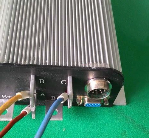
Examples of wiring between a Motor Controller and a BLDC motor
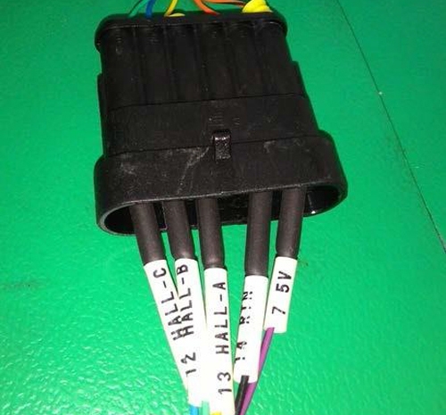
The brushless DC motor signal terminal is a type D quick plug-in, and the PIN is in the black rubber cover. If you cannot see the PIN, you can take off the rubber cover.
Motor Terminal → Controller Terminal
| Red | Motor U | White plastic case | → | A pile |
| Yellow | Motor V | Green plastic case | → | B pile |
| Blue | Motor W | Blue plastic case | → | C pile |
Signal Lines
| Controller Line Color | Controller Line Definition | Pin No. | → | Hall Line Color | Hall Line Definition | Pin No. |
| Purple | 5V | 7 | → | Red | 5V | 1 |
| Black | 0V | 14 | → | Black | 0V | 2 |
| Yellow | Hall A | 13 | → | Yellow | Hall A | 4 |
| Green | Hall B | 12 | → | Blue | Hall B | 5 |
| Blue | Hall C | 11 | → | Green | Hall C | 6 |
Wiring Diagram
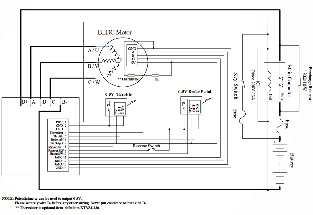
Motor Lines
Signal Lines
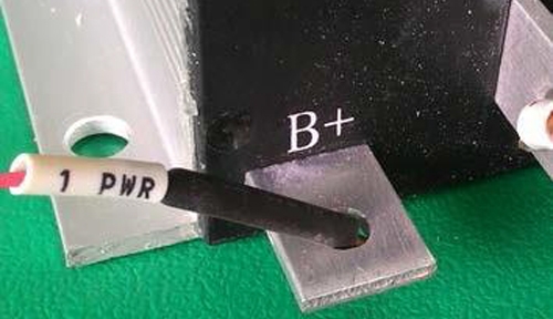
After the wire connecting the motor to the controller is completed, power is connected to the controller's B+ (24V+,48V+,72V+…), B- pile(0V).
1. No. 1 (PWR) of the controller harness is connected to B+, is controlled by the on/off switch, and enables controlled start-up.
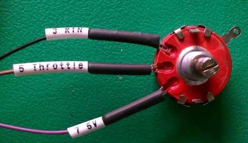
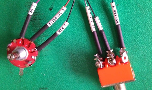
2. Wire harness 3 (RTN), 5 (THROTTLE), 7 (5V) connectors, potentiometer.
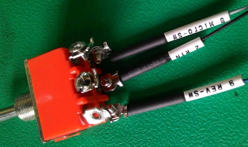
3. The no. 2 and no. 8 connectors are one operating direction of the motor, and the no. 2 and no. 9 connectors are the reverse.
More BLDC Motor & Controller Wiring Details
How to Control a BLDC Motor: Start, Speed, and Reverse?
This video guides you through the complete process of wiring, configuring, and operating a 24V BLDC motor using a controller, power supply, and a control box with Start and Emergency Stop buttons. You’ll learn how to connect the components, implement safety functions, control and adjust motor speed, and easily switch the rotation direction, making it perfect for robotics, automation projects, or anyone new to motor control.
How to Control a BLDC Motor Using RS485 Modbus-RTU?
How to Control BLDC Motor Speed with a Potentiometer?
How to Control BLDC Motor with an Analog Voltage Input?


