
If you are looking to achieve precise, automated control over a Brushless DC (BLDC) motor without relying on manual potentiometer tuning, using RS485 communication is a game-changer. In this tutorial, we will walk you through the complete step-by-step process of setting up a BLDC motor control circuit, wiring your hardware, configuring your controller, and using PC software to execute speed and direction commands.
Watch the video below for a complete tutorial.
Components Required
Before getting started, make sure you have the following hardware and software ready:
- BLDC Motor (with built-in Hall sensor)
- BLDC Motor Controller
- 24V DC Switching Power Supply
- RS485-to-USB Converter
- PC with dedicated BLDC control software installed
Note: The brushless DC motor requires an electronic controller to regulate speed and direction. The power supply powers both the system, while the RS485-to-USB converter bridges communication between the controller and your PC.
Step 1: Circuit Diagram & Hardware Wiring
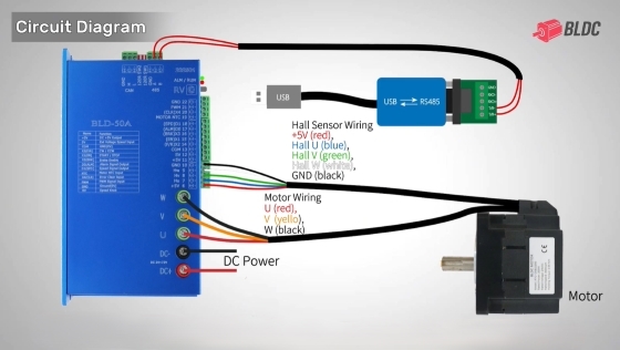
Wire up your system carefully following the connection guidelines:
- Power Supply: Connect the 24V DC power supply to the designated power terminals on the controller.
- Motor Phases: Connect the motor’s three-phase wires (U, V, W) to the corresponding controller terminals.
- Hall Sensor: Plug the BLDC motor's Hall sensor cable into the appropriate pins on the controller.
- RS485 Communication: Wire the RS485 converter to the controller’s RS485 ports, ensuring correct polarity (A to A+, B to B–).
Step 2: Controller Configuration
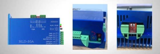
Before powering everything on, configure the hardware switches on the controller:
- RV Terminal: Turn off the potentiometer (RV) terminal since we are using RS485 for digital speed control instead of manual adjustments.
- DIP Switches: Set SW1 and SW2 to OFF by toggling both switches up.
Step 3: RS485 Communication & Software Setup
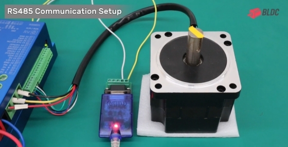
- Double-check the RS485 polarity (A to A+, B to B–) to prevent communication errors.
- Power on your system, then plug the RS485 converter into your PC's USB port.
- Open your BLDC control software, navigate to Com Setting, and click Connect.
- The software should auto-detect the correct COM port (e.g., COM5) and baud rate (default: 38400). Once connected, the software will automatically read parameters from the controller.
Troubleshooting Tip: If the connection fails, verify your port in Windows Device Manager and double-check that the controller's address matches the software setting (default: 01).
Step 4: Parameter Settings & Motor Control
To unlock digital control via RS485, you need to configure specific parameter registers in the software.
1. Communication Channels Setup
First, configure the fundamental communication protocol by setting the data and control channels:
- PN14 (Data Channel): Set to 2 (Selects the SV analog input as the data source).
- PN15 (Control Channel): Set to 2 (Selects the I/O switch as the control source).
(Setting both to 2 enables standard MODBUS communication).
2. Speed and Direction Control (PN58)
Parameter PN58 (Data A) governs both the rotational speed and direction of the BLDC motor (input range: 0 to 65535).
Here is how to calculate and execute different motion commands:
| Operation Mode | Calculation / Formula | Action in Software | Example Input |
| Clockwise (Forward) | Direct input of desired speed | Enter speed directly in "New value", then click Write param | 300 (for 300 rpm) |
| Counterclockwise (Reverse) | 65535 – [Desired Speed] | Subtract speed from 65535, enter result, and click Write param | 65235 (for -300 rpm, i.e., 65535 - 300) |
| Stop Motor | Fixed value 0 | Enter 0 to bring the motor to a complete stop | 0 |
Real-Time Monitoring: You can verify performance and check the actual speed under the Device Information tab (e.g., Pn137-Speed). If values do not update immediately, simply click refresh.
3. Speed Limits & Safety Range (PN68 & PN69)
You can define safe operating boundaries for your motor to prevent over-speeding:
- PN68 (Max Speed Limit): Default upper limit is set to 3500 rpm.
- PN69 (Min Speed Limit): Default lower limit is set to 200 rpm.
Important Note on Out-of-Range Values: Any value entered outside this safety window will automatically default to the limits. For instance, testing an extreme low value like 100 rpm will cause the motor to maintain the minimum limit of 200 rpm (which you can verify via Pn137-Speed).
Got Questions?
If you encounter any issues during the RS485 setup or parameter configuration, feel free to contact us!


