
A BLDC motor control circuit enables speed and direction control through communication interfaces such as RS485 and CAN. In this guide, we’ll walk through the required components, circuit wiring, controller configuration, CAN command transmission, and real-time motor status monitoring.
You can check the video down below for more instructions:
Components Required
To build this setup, you’ll need five key components:
- BLDC electric motor
- BLDC motor controller
- 24V DC switching power supply
- USB to RS485 converter (for serial communication)
- USB-CAN analyzer (for CAN bus control)
Make sure all components are rated for compatibility. If you’re unsure, visit our website and consult our technical experts for specification details.
The 24V DC power supply energizes the electric motor and motor driver. The USB-to-RS485 converter and USB-CAN analyzer act as communication bridges, allowing the BLDC motor controller to receive commands from a PC via RS485 or CAN. This setup enables control over the motor’s speed and direction.
Circuit Wiring
Connect the components according to the wiring diagram.
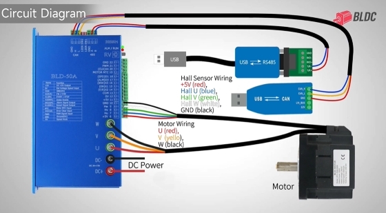
1. Power supply and motor connections
First, connect the 24V DC power supply to the controller, ensuring correct polarity. Then connect the BLDC motor’s three-phase wires (U, V, W) to the controller.
If your motor has a Hall sensor, connect it to the Hall input terminals on the controller.
2. Communication connections
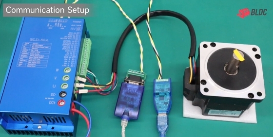
Connect the communication devices to the controller’s designated ports:
- CAN communication: Connect CAN_H and CAN_L to the controller’s CAN ports.
- RS485 communication: Connect the A/B lines to the controller’s RS485 ports.
Ensure all wiring is properly connected according to the wiring diagram.
Controller Configuration and Software Setup
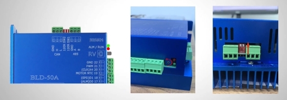
Before proceeding, disable the RV terminal on the controller because the setup uses RS485 for speed control instead of manual potentiometer control. Set SW1 and SW2 DIP switches to OFF.
Next, power up the system and connect both communication devices to your PC via USB.
1. Establish the COM Connection
Launch the BLDC control software and navigate to COM Setting. Click Connect to establish the COM connection.
Once the software finishes reading the parameters, the BLDC motor controller is successfully connected.
If the connection fails, check the following settings:
- Controller address (default: 01)
- Baud rate (default: 38400)
- COM port in Device Manager under Ports (COM & LPT)
2. Configure the CAN Parameters
Go to Parameter Setting and set PN14 and PN15 to 3. This configures CANBUS as both data and control input.
Then open the CAN software tool and click Continue. From the Select Device dropdown, choose your device (e.g., USBCAN2).
Keep the default baud rate at 500kbps and click OK and Start CAN. Upon successful connection, the system will automatically begin receiving heartbeat signals.
Click Pause to stop the data stream from scrolling. The video identifies the real-time motor status feedback with 00 as the CAN ID.
Sending CAN Motor Control Commands
Use the extended frame format and ensure the frame ID matches the controller’s communication ID (e.g., 18705500).
The target data determines the motor speed and direction:
- Bit0-13 is responsible for target speed control.
- Bit14-15 controls motor direction.
For proper command transmission, Byte 6 must differ from the previous command. Byte 7&8 must equal the checksum of Byte 1–6 to prevent transmission errors.
Set Send Interval to 1000ms before sending commands.
| Command 1: 3000 RPM Counterclockwise Rotation |
To send a 3000 RPM counterclockwise rotation command, use the following target data:
Click Continue and Send to transmit the frame. You can then pause the incoming data stream to inspect the motor status and command feedback. |
| Command 2: Stop the Motor |
To stop the motor, send a stop command with the target data set to 0x00.
Ensure that Byte 6 differs from the previous command. Click Continue and Send to execute the command. The motor should stop running. Click Pause to stop data transmission. |
| Command 3: 500 RPM Forward Rotation |
To issue a new command for 500 rpm forward rotation, use the following target data:
Always recalculate and update the checksum before sending. Click Continue, then Send to issue the command. The system should respond with state feedback. |
Monitoring Motor Status
The controller sends back real-time status data, including the following information.
|
Frame ID: 0x18700055 Received status data example: 0x 17 00 46 0b af 00 01 17 The video provides the following interpretation:
|
This feedback shows the reported bus voltage, bus current, controller temperature, actual motor speed, and fault status.
Conclusion
This guide covers the process of building a Brushless DC motor control circuit using RS485 and CAN communication, from component connections and controller configuration to CAN command transmission and real-time status monitoring.
Whether you’re building a prototype or integrating a motor into an industrial environment, these steps provide an overview of the control process.


