
A potentiometer is a simple way to adjust BLDC motor speed without using a complicated control system. By turning the knob, you can change the speed manually, making it useful for applications where local speed adjustment is all you need.
In this article, we'll walk through the basic wiring, DIP switch settings, and setup process for controlling a BLDC motor with a potentiometer, including forward and reverse rotation.
For a visual demonstration of the wiring and live testing steps, check out the video guide: BLDC Motor Speed Control with Potentiometer.
What Do You Need for the Setup?
Before getting started, prepare the following components:
- BLDC motor controller
- BLDC motor
- DC power supply
- Potentiometer
- Control box with Start and Stop buttons
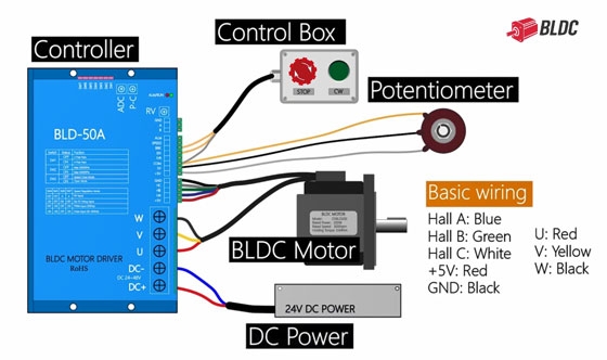
Make sure the brushless motor, motor controller, and power supply are compatible before connecting anything. Check the motor controller’s wiring diagram for the correct terminals and wire connections.
Set DIP Switches for External Speed Control
The motor controller's DIP switches determine how the motor responds to external control signals. For the controller shown in this setup, turn DIP switches 4 and 6 ON to enable external speed adjustment using the potentiometer. Keep in mind that DIP switch functions vary between controller models. Check the relevant manual before changing the settings.
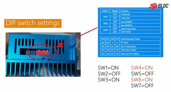
Note: The DIP switch settings provided in this article are specific to the motor controller used in this tutorial and may not apply to other models. Always refer to your controller’s wiring diagram and manufacturer’s instructions for the correct switch settings and configuration.
Potentiometer Wiring for a BLDC Motor Controller
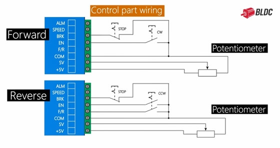
The potentiometer connects to the motor controller's COM, SV, and +5V terminals. These connections allow the motor controller to receive a speed reference from the potentiometer.
Before wiring the potentiometer, connect the BLDC motor's Hall sensor wires and power wires according to the motor controller's wiring diagram. The wire colors and terminal assignments may vary by model, so always refer to the documentation for your specific equipment.
For both forward and reverse control setups, the potentiometer uses the same three terminals:
- COM: Common terminal
- SV: Speed control signal input
- +5V: Reference voltage output
Connect each wire to its designated terminal and double-check the connections before powering up the system.
Adjust BLDC Motor Speed with a Potentiometer
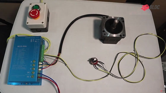
Once the wiring and switch settings are complete, you can test the setup.
- Turn on the DC power supply.
- Press the Start button on the control box.
- Slowly turn the potentiometer knob.
- Observe how the motor speed changes as you adjust the knob.
Turning the potentiometer changes the speed command sent to the motor controller. Within the BLDC motor's supported operating range, the controller adjusts the motor speed accordingly. If the brushless DC motor doesn't respond as expected, check the potentiometer wiring, DIP switch settings, and controller configuration before trying again.
Set Up Forward and Reverse Rotation
The potentiometer controls speed, while the controller's direction control determines whether the motor rotates forward or in reverse. For both forward and reverse setups, connect the potentiometer to COM, SV, and +5V as described above. Configure the direction control according to your controller's wiring diagram.
Before switching direction, follow the controller manufacturer's instructions. Some controllers require the motor to stop before the direction command is changed.
When Should You Use a Potentiometer for BLDC Motor Speed Control?
A potentiometer works well when an operator needs to adjust motor speed manually at the equipment itself. It's a straightforward option for test benches, small machines, and other systems where remote speed control or automated adjustment isn't necessary.
However, a potentiometer is not suitable for every control setup. Make sure its resistance value and wiring match the controller's specifications. In most controller-based BLDC systems, the potentiometer provides a low-power speed reference signal rather than supplying power directly to the motor. For applications that require remote operation, programmable speed settings, or automated control, other input methods may be more appropriate.
Need a BLDC Motor for Your Project?
The right BLDC motor and controller make speed adjustment easier and help ensure the system works as expected. We offer brushless DC motors in different voltage ratings, sizes, and configurations for a wide range of applications.
Visit BLDC.com to explore our BLDC motor options and find a suitable solution for your application.


