
Controlling a brushless DC (BLDC) motor involves connecting the motor to a controller and configuring the control inputs. In this article, we’ll demonstrate how to wire a BLDC motor system, start and stop the motor, adjust its speed, and switch between forward and reverse rotation.
Watch the complete video: BLDC Motor Control Tutorial: Start/Stop, Speed & Reverse Setup
1. Components and Wiring
The setup requires four main components:
- BLDC motor
- BLDC Motor controller
- DC power supply
- Control box
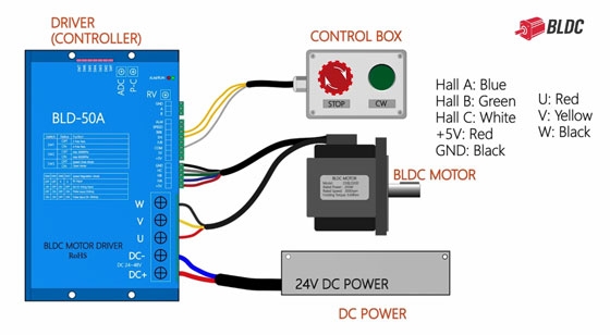
Connect the Hall sensor wires, motor power wires, and control wires to their corresponding terminals. The wires have different colors and diameters, so check their positions against the wiring diagram.
2. Forward Rotation and Start/Stop Control
For forward rotation, start by connecting the wires according to the wiring diagram. In this setup, BRK is assigned for the emergency stop function, while the EN terminal starts the motor and enables forward rotation when connected to COM.
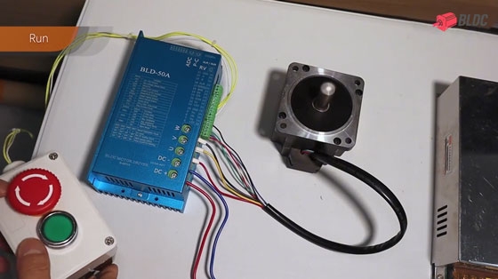
After all connections are completed, double-check the wiring before operation. The red and blue wires are used for power connection; the wire bundle contains the motor power and Hall sensor wires, and the yellow wires are connected to the control box.
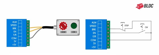
Follow these steps to operate the BLDC motor:
- Press the green self-locking button to start the motor.
- Press the emergency-stop button to stop the motor immediately.
- Reset the emergency-stop button to restore operation.
- Release the green button to stop the motor normally.
3. Adjusting the Motor Speed
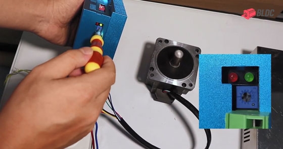
The BLDC motor controller features a speed adjustment control. Simply turn the adjustment screw with a screwdriver to increase or decrease the motor speed and check the motor’s response.
4. Switching to Reverse Rotation
The BRK connection remains configured for the emergency-stop function. To reverse the motor's rotation, connect both EN and F/R to COM as shown in the wiring diagram. Start the brushless motor and observe the change in rotation direction. The motor now runs in reverse, and its speed can be adjusted using the RV control.
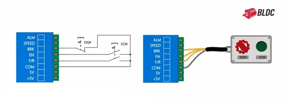
Note: The terminal connections described here apply to the controller shown in this demonstration. Check the corresponding wiring diagram when using a different controller.
BLDC.com offers brushless DC motors in various power ratings, sizes, and configurations for applications such as drones, robotics, electric vehicles, and industrial equipment. If your project requires specific operating parameters or installation dimensions, custom motor options are also available.


