
A BLDC motor controller can support multiple control methods, allowing users to manage motor speed, direction, and operating parameters in different ways. In some applications, combining these methods provides greater flexibility than using a single control source.
In this article, we'll show you how to build a BLDC electric motor control system that combines RS485 communication, PWM frequency input, and I/O switching. The system uses a PWM signal generator to adjust brushless DC motor speed, a rocker switch to control brushless motor start/stop and direction, and a PC to configure motor controller parameters through RS485.
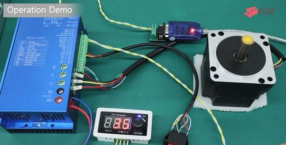
For a practical demonstration of the wiring, software configuration, and motor operation, watch the video: BLDC Control 3 Ways – RS485 + PWM Frequency + I/O in One Circuit.
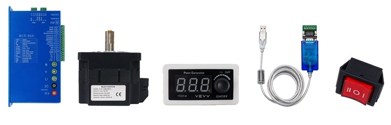
Components Required
Prepare the following components before starting the setup:
- BLDC motor
- Compatible BLDC motor controller
- 24V DC switching power supply
- USB-to-RS485 converter
- PWM signal generator
- Rocker switch
- PC with the appropriate BLDC control software
Make sure the BLDC motor, motor controller, and power supply are compatible with each other. The terminal assignments and configuration settings in this tutorial apply to the specific motor driver used in the video.
How Does This BLDC Motor Control System Work?
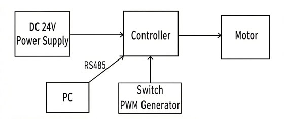
The system combines three control methods, each serving a different purpose.
- RS485 communication: Connects the motor controller to a PC for reading and configuring controller parameters.
- PWM frequency input: Provides the speed command through an external PWM signal generator.
- I/O switching: Uses a rocker switch to control BLDC motor enable and forward/reverse direction.
With this arrangement, you can adjust the brushless DC motor speed using the signal generator while controlling its operating state and direction through the switch. RS485 provides access to the controller's configuration parameters.
Step 1: Connect the Motor Controller and Power Supply
First, connect the 24V DC power supply to the motor controller's power input terminals.
Next, connect the BLDC motor's three-phase wires to the motor controller terminals marked U, V, and W. If your brushless motor uses Hall sensors, connect the Hall sensor wiring according to the controller's wiring diagram.
Before applying power, check all connections carefully. Disconnect the power supply while wiring the system, and verify the electric motor and controller wiring before proceeding.
Step 2: Connect the PWM Signal Generator
The PWM signal generator provides the motor speed command.
Power the PWM signal generator using a suitable DC supply. Connect its PWM output to the controller's designated PWM input and its ground to the controller's GND terminal, following the wiring diagram for the controller used.
In the demonstration, the BLDC motor speed is adjusted by changing the PWM input frequency through the signal generator.
Important: The motor controller used in the video supports a PWM frequency range of 1 kHz to 10 kHz. Operating outside this range may trigger an over-frequency alarm. Check your controller's manual before selecting the signal frequency and signal levels.
Step 3: Wire the Rocker Switch for Enable and Direction Control
The rocker switch connects to the motor controller's X1, X2, and COM terminals.
- X1: Motor start/stop control
- X2: Forward/reverse direction control
- COM: Common terminal for the I/O control signals
The switch changes the state of the corresponding control inputs, allowing you to enable the motor and change its rotation direction.
The exact switch wiring depends on the motor controller's input logic and the rocker switch configuration. Refer to the controller's wiring diagram before connecting these terminals.
Step 4: Connect the Controller to the PC through RS485
Use a USB-to-RS485 converter to establish communication between the motor controller and the PC.
Connect the converter's A and B terminals to the corresponding RS485 terminals on the controller. The A/B polarity conventions can vary between devices, so confirm the terminal definitions in the documentation for both the converter and controller.
Then connect the converter to the PC's USB port.
Before continuing, check the controller configuration used in the video:
- Ensure the RV terminal is turned off.
- Set DIP switches 1 and 2 to OFF.
These settings are specific to the motor driver shown in the demonstration. Other controller models may require different DIP switch positions or control-source settings.
Step 5: Establish the RS485 Connection
Open the BLDC controller software on your PC.
Go to COM Setting, select the COM port assigned to the USB-to-RS485 converter, and click Connect.
If the connection is successful, the software displays “COM connect success.” After the controller parameters have been read, “Parameters read to file success” confirms that the software has completed the parameter-reading operation.
If the connection fails, check the following:
- Whether the correct COM port is selected
- Whether the RS485 A and B connections are correct
- Whether the controller's communication address and serial communication settings match the software
- Whether the USB-to-RS485 converter is properly recognized by the PC
Consult the motor controller manual for the required communication settings.
Step 6: Configure the BLDC Controller Parameters
Once communication is established, open Parameter Settings and configure the following parameters for the controller used in the video.
| Parameter | Setting | Function |
| PN14 | 5 | Selects PWM frequency as the speed input source |
| PN15 | 1 | Selects I/O switching as the control source |
| PN30 | 0 | Assigns X1 to motor start/stop control |
| PN31 | 1 | Assigns X2 to direction control |
| PN02 | 3000 (example) | Sets the maximum motor speed under PWM control |
After entering a new value, click Write Parameter to apply the setting. Follow the software instructions to ensure the parameters have been written successfully.
PN02 is set to 3000 rpm in this example, so the configured maximum speed is 3000 rpm. The actual motor speed depends on the controller settings and the PWM input.
The video demonstrates an adjustable speed range of 300 to 6000 rpm. This range should not be assumed to apply to every controller or motor configuration.
Note: Parameter numbers, available values, DIP switch settings, and terminal functions are controller-specific. Always check the user manual for your motor controller or driver model before changing parameters.
Step 7: Test the BLDC Motor
After checking the wiring and configuration, power up the system and perform the following tests.
- Start the motor: Move the rocker switch to position I to enable the motor, then activate the PWM signal generator. The BLDC motor should start when the required enable conditions and PWM input are present.
- Adjust the motor speed: Turn the signal generator knob to change the PWM frequency. The controller uses this frequency input to regulate the motor speed. In the video, the displayed PWM frequency is approximately 3.5 kHz. Observe the motor response as you adjust the input, and keep the frequency within the supported range.
- Reverse the motor direction: Move the rocker switch to position II to change the direction command through the X2 input. Confirm that the BLDC motor responds as expected. Follow the motor controller's instructions for direction changes, particularly if the motor is already running.
- Verify RS485 communication: The PC connection can be used to read or configure supported controller parameters. If the brushless DC motor does not respond as expected, check the selected control sources, parameter values, I/O states, and PWM input before troubleshooting further.
Conclusion
Combining RS485 communication, PWM frequency input, and I/O switching provides a flexible way to control a brushless DC motor.
In this setup, the PWM signal generator adjusts speed, the rocker switch manages motor enable and direction, and RS485 communication allows parameter configuration from a PC.
This approach can be useful when an application requires separate speed and direction controls alongside access to the BLDC motor controller's configuration settings. Before building the circuit, confirm that your motor controller supports all three methods and follow its specific wiring and configuration instructions.


