
The I/O + SV control method allows you to control a BLDC motor’s start/stop, speed, and direction using a rocker switch and a potentiometer. The switch manages BLDC motor operation and direction, while the potentiometer adjusts speed through the motor controller’s SV input.
Follow the steps below to learn how to wire the components, configure the motor controller, and operate the BLDC motor.
Watch the full video tutorial: BLDC Motor I/O + SV Control.
How Does I/O + SV Control Work?
I/O + SV control uses digital input signals and an analog voltage signal to control a BLDC motor.
- I/O (Input/Output): The motor controller's digital input terminals handle functions such as motor enable and direction control. In this setup, a rocker switch connects the corresponding terminals.
- SV (Speed Voltage): The SV input receives an analog voltage signal for speed adjustment. A potentiometer varies the voltage at its wiper terminal, allowing the controller to adjust motor speed according to the input signal.
With this arrangement, you can use the rocker switch to start or stop the BLDC motor and change its direction, while the potentiometer adjusts the speed. The exact functions of the I/O terminals and the SV input depend on the controller model.
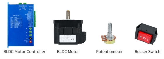
Components Required
Prepare the following components before wiring:
- BLDC electic motor
- Compatible BLDC motor controller
- Potentiometer
- Rocker switch
- 24V DC power supply
- Connecting wires
Make sure the BLDC motor, controller, and power supply are compatible with each other before connecting the circuit.
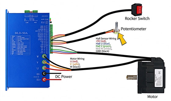
How to Wire the Potentiometer and Rocker Switch
Before making any wiring connections, disconnect the power supply and make sure the controller is de-energized. Follow the wiring diagram for your specific controller model.
Connect the Power Supply and Motor
Connect the positive and negative terminals of the 24V DC power supply to the motor controller’s designated power input terminals. Next, connect the brushless motor phase wires to the corresponding U, V, and W output terminals on the controller.
If your BLDC motor uses Hall sensors and your controller supports Hall feedback, connect the Hall sensor wires to the designated Hall sensor terminals according to the wiring diagram.
Connect the Potentiometer to the SV Terminal
The potentiometer provides the analog voltage signal used for speed adjustment.
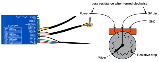
Connect the three potentiometer terminals as follows:
- +5V: One end of the potentiometer
- COM: The other end of the potentiometer
- SV: The potentiometer wiper, which provides the adjustable voltage signal
When you rotate the potentiometer, the wiper voltage changes. The motor controller reads this signal and adjusts the motor speed accordingly.
Use only the reference voltage and signal terminals specified in the controller's wiring diagram. Do not connect the potentiometer to the 24V power supply unless explicitly specified by the manufacturer.
Connect the Rocker Switch to the I/O Terminals
The rocker switch controls the motor enable and direction inputs through the motor controller’s COM terminal.
- X1 (EN): Motor enable input
- X2 (F/R): Forward/reverse input
- COM: Common terminal for the control signals
Depending on the switch position, COM connects to either X1 or X2 to control BLDC motor operation. Before wiring, verify the terminal assignments and input logic in your motor controller’s wiring diagram.
Configure the Motor Controller
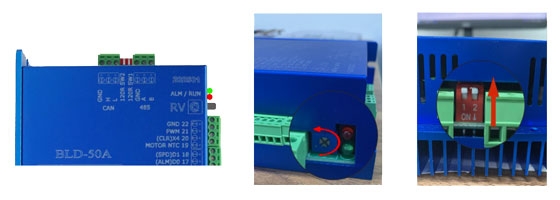
Before operating the brushless DC motor, configure the motor controller according to the instructions for the model shown in the video.
- Turn the RV adjustment screw counterclockwise to its fully off position.
- Set SW1 and SW2 to OFF.
- Check all power, motor, Hall sensor, and control signal connections before reconnecting the power supply.
These settings are specific to the controller demonstrated in the video. Other motor controllers may require different speed-reference settings or DIP switch configurations.
How to Operate the BLDC Motor
Once the wiring and controller settings are complete, you can test the circuit.
- Start the Motor: Move the rocker switch to position II to connect COM to X1 (EN), enabling the BLDC motor. Rotate the potentiometer to adjust the motor speed.
- Stop the Motor: Move the rocker switch to position O to disable the motor. Wait until the motor has stopped completely before changing the direction command.
- Change the Motor Direction: Move the rocker switch to position I to connect COM to X2 (F/R) and change the direction command. The potentiometer remains available for speed adjustment.
The BLDC motor's actual response depends on the motor controller's input logic and configuration. Follow the operating instructions for your controller, and do not change the direction command while the BLDC motor is running unless the controller supports this operation.
Note: The wiring connections, rocker switch positions, and DIP switch settings shown in this tutorial apply only to the BLDC motor controller demonstrated in the video. Other controllers may have different terminal assignments, signal voltage requirements, switch logic, and configuration methods. Always refer to the user manual for your specific controller model before connecting components or changing settings.
Conclusion
The I/O + SV method provides a straightforward way to control BLDC motor operation using a rocker switch and a potentiometer. The switch handles motor enable and direction commands, while the potentiometer adjusts speed through the controller’s SV input.
With the correct wiring and motor controller configuration, this setup can be used in applications that require simple, manual BLDC motor control.


