
Setting up a BLDC motor for a DIY electric bike drive system requires a BLDC motor, a compatible motor controller, a DC power supply, and several control components. This article covers the wiring for the brushless DC motor, pedal throttle, start button, and forward/reverse switch.
For a visual demonstration of the wiring and live testing steps, check out the video guide: BLDC Motor Setup for DIY E-Bike Drive System.
Components Required
Prepare the following components:
- High-torque BLDC motor
- Compatible BLDC motor controller
- DC power supply
- Pedal throttle with an analog potentiometer
- Push-button switch
- Forward/reverse toggle switch
- Supporting wires and connectors
Check the BLDC motor and controller specifications to ensure they are compatible before installation.
Connecting the BLDC Motor and Controller
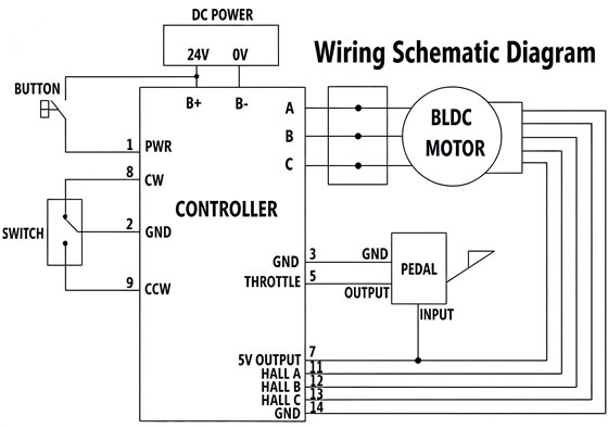
- Connect the Motor Phase Wires
Connect the BLDC motor's three phase wires to the controller:
-
- Red to terminal A
- Yellow to terminal B
- Blue to terminal C
Then connect the brushless motor's Hall sensor cable to the corresponding controller connector. Wire colors and terminal assignments may vary, so check the wiring diagram for your specific model.
- Connect the DC Power Supply
Connect the positive supply to B+ and the negative supply to B- on the controller. Keep the power supply disconnected while making connections, and verify the voltage and polarity before powering on.
Wiring the Start Button
In this setup, connect the brushless controller's PWR (line 1) to B+ through the push-button switch. Pressing the button enables the controller. In the video, the indicator changes from red to green when the controller is enabled. Confirm whether your controller requires a momentary or maintained switch connection.
Wiring the Forward/Reverse Switch
The direction switch uses lines 8 and 9 with line 2 to select forward or reverse rotation. Check the controller wiring diagram to confirm the terminal assignments. Stop the brushless electric motor before changing direction unless the controller specifically supports direction changes while running.
Connecting the Pedal Throttle
The pedal throttle uses three wires to provide power, ground, and a speed signal.
| Pedal wire | Controller Connection | Function |
| Red | Line 7 (5V output) | Power supply |
| Green | Line 5 (Throttle) | Speed signal |
| Yellow | Line 2 or Line 3 (GND, as specified) | Ground |
Verify the pinout before connecting the wires, particularly the ground terminal. When the pedal is pressed, it sends a variable signal to the controller. Pressing it farther increases the throttle command and electric motor speed within the system's operating limits.
Testing the BLDC Motor
After checking all connections, follow these steps:
- Apply power to the controller.
- Press the start button to enable the controller.
- Select the desired rotation direction.
- Slowly press the pedal and observe the motor speed.
- Release the pedal and confirm that the motor slows or stops as expected.
- Stop the BLDC motor before selecting the opposite direction, then test again.
If the brushless DC motor does not start or runs abnormally, check the power supply, phase wires, Hall sensor connections, throttle signal, and controller enable input.
Note: The wiring connections and DIP switch settings in this article apply only to the motor controller shown in the video. Other controllers may have different terminal assignments and control methods. Always check your controller’s wiring diagram and user manual before connecting wires or configuring settings to avoid incorrect wiring or potential damage.
Conclusion
A BLDC motor controller coordinates power delivery, pedal throttle input, start/stop control, and rotation direction in a DIY e-bike drive system. Correct wiring and controller configuration are essential for reliable operation. Always verify compatibility and follow the manufacturer's instructions before testing.


