
RS485 Modbus RTU allows you to control a BLDC motor from a PC or host system. With the correct wiring and communication settings, you can set motor speed, change rotation direction, read speed feedback, and stop or restart the BLDC motor.
This guide covers the hardware connections, communication setup, and basic Modbus RTU commands demonstrated in the video tutorial.
Watch the full video tutorial: BLDC Motor Control with RS485 Modbus-RTU.
Hardware Required for RS485 BLDC Motor Control
Before getting started, prepare the following equipment:
- BLDC motor
- Compatible BLDC motor controller with an RS485 interface
- DC power supply
- RS485-to-USB converter
- PC or host computer with serial communication testing software
The RS485-to-USB converter connects the motor controller to the computer, allowing you to send commands and read data through the Modbus RTU protocol.
RS485 Wiring Connections
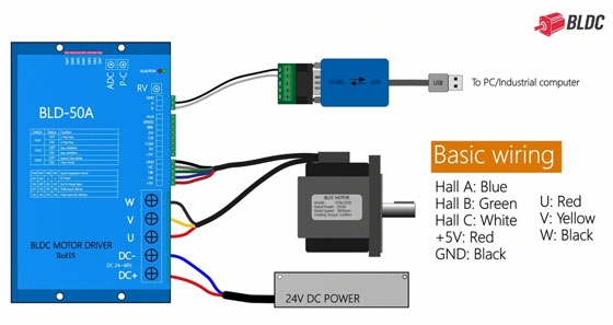
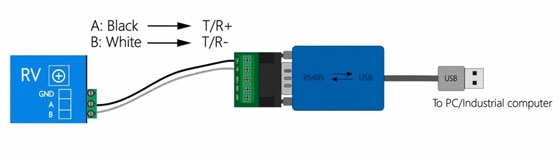
Start by connecting the RS485 interface on the motor controller to the RS485-to-USB converter.
The wiring connections are:
| BLDC motor controller | RS485-to-USB converter |
| RS485 A | T/R+ |
| RS485 B | T/R− |
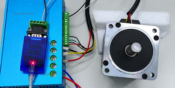
Connect the converter to the PC through its USB port. Then connect the BLDC electric motor and DC power supply to the controller according to the wiring diagram for your specific model.
Before powering on the system, check that all connections are secure and that the A and B communication lines are correctly connected. The DIP switch setting also needs attention. In the video, DIP switch SW3 is set to OFF for speed closed-loop control mode. Check your controller's manual to confirm the correct DIP switch setting for your model.
Modbus RTU Communication Setup
Once the hardware is connected, open the serial communication testing software on your PC. First, identify the COM port assigned to the RS485-to-USB converter. You can find it in Windows Device Manager under Ports (COM & LPT).
Configure the communication software using the following settings:
- COM port: Select the port assigned to your converter
- Baud rate: 38400
- Protocol: Modbus RTU
- Command format: Hexadecimal (Hex)
The station number, baud rate, and other communication parameters must match the settings of your motor controller. The baud rate of 38400 is the value used in this tutorial. After entering the settings, open the serial connection.
Modbus RTU Protocol Parameters
| Function Code | Data Address | Function Description | Data Meaning |
| 06 (Write command) | 00 B6 Hex | RS485 Function | 0: Invalid (default); 1: Valid |
| 06 (Write command) | 00 56 Hex | Speed Data Area | 0~9999 |
| 06 (Write command) | 00 66 Hex | Motor Status Data Area | 0: Motor Stop; 1: Forward; 2: Reverse |
| Function Code | Data Address | Read 2byte | Read Value Meaning |
| 03 (Read command) | 00 56 Hex | 00 01 Hex | Motor speed |
Enabling the Controller's RS485 Interface
Before sending speed or direction commands, you need to enable the controller's RS485 interface. Modbus RTU provides different function codes for reading and writing registers. Two commonly used codes in this tutorial are:
- Function code 06: Write a single register
- Function code 03: Read holding registers
Use function code 06 to write the required command to the controller's register used to enable the RS485 interface. In the video, the software displays A9 EC as the returned check code, indicating that the command was accepted and the RS485 interface was opened on the controller used in the tutorial.
Setting the BLDC Motor Rotation Direction
After opening the RS485 interface, you can send a command to set the brushless motor's rotation direction. In the video, the rotation direction is controlled through register address 00 66.
To set forward rotation, write the value:
00 01
Use Modbus function code 06 to write this value to the register 00 66. If the returned register value matches the value sent, the write operation has been completed correctly. For reverse rotation, the video uses the value 00 02 at the same address.
Setting and Reading the BLDC Motor Speed
The motor controller uses register address 00 56 for speed setting and speed reading in this example.
Setting the motor speed to 1000 rpm
To command the motor to run at 1000 rpm, write the hexadecimal value 03 E8 to register 00 56 using function code 06. The BLDC motor should start rotating after the command is executed, provided that the controller is enabled and the system is operating normally.
Reading the current motor speed
To check the speed, use Modbus function code 03 to read the value from register 00 56. The returned hexadecimal value is 03 E7, which equals 999 in decimal. According to the speed register definition used by this controller, this corresponds to 999 rpm.
The reported value is one count lower than the 1000 rpm command in this example. The relationship between the commanded and reported speed depends on the controller's register definitions and settings.
Stopping and Restarting the BLDC Motor
There are two methods demonstrated in the video for stopping the BLDC motor.
Method 1: Set the speed to zero
Use function code 06 to write 00 00 to register 00 56. This sets the speed command to zero, causing the motor to stop as demonstrated in the video. To restart the motor, write a nonzero speed value to the same register.
Method 2: Send the stop command
Alternatively, write 00 00 to register 00 66 using function code 06. In the video, this command is used to stop the motor. To restart it, write 00 01 for forward rotation or 00 02 for reverse rotation to the same register.
Important: Do not change the rotation direction while the BLDC motor is running unless the motor controller manual confirms that this operation is supported.
Modbus RTU Check Codes
Modbus RTU messages include a CRC check value to help detect communication errors.
Some serial communication testing software can calculate the CRC automatically when the CRC field is left blank. In the video, the calculated CRC value is 69 64 for the specific message shown. This value should not be reused for other messages without recalculating the CRC.
If you enter the CRC manually, make sure it matches the complete message. An incorrect CRC may cause the controller to reject the command. The expected response also depends on the function code, register address, station number, and command being sent.
Troubleshooting RS485 BLDC Motor Control
If the BLDC motor does not respond to your commands, check the following items before changing the control settings:
- Wiring: Confirm that RS485 A and B are connected to the corresponding converter terminals.
- COM port: Make sure the software is using the correct port for the USB converter.
- Communication settings: Verify the baud rate, Modbus RTU mode, and station number.
- RS485 interface: Confirm that the controller's RS485 port has been opened as required.
- Command format: Check the function code, register address, data value, and CRC.
- Controller settings: Confirm the DIP switch configuration and operating mode for your controller model.
- Motor operation: Check the power supply, controller status, and motor connections if communication is working but the motor does not rotate.
Always refer to the wiring diagram and register map for your specific controller. Register addresses, speed commands, rotation settings, and DIP switch functions may differ between models.
Note: The DIP switch settings, register addresses, command values, and check codes shown in this article apply to the specific BLDC motor controller used in the video. Other controllers may use different DIP switch configurations, register maps, and communication settings. Always refer to your controller's user manual before changing DIP switches or sending commands.
Conclusion
RS485 Modbus RTU provides a practical way to control a brushless DC motor from a PC or host computer. Once the wiring and communication parameters are configured, you can use register commands to set the rotation direction, adjust the speed, read the current speed, and stop or restart the motor.
The commands and register addresses in this guide are based on the controller shown in the video. BLDC.com offers BLDC motors and compatible controllers for a range of motion control applications. Contact our team if you need help selecting a brushless motor and controller for your application.


