
RS485 communication allows users to configure multiple preset speeds and motor directions for a brushless DC (BLDC) motor. Combined with two external self-latching buttons, this setup lets users switch between three preset speed segments without manually adjusting a potentiometer.
In this tutorial, we'll demonstrate the complete wiring, controller parameter configuration, and operation process using an RS485 connection and a PC.
For a practical demonstration of the wiring, software configuration, and motor operation, watch the video: BLDC Motor Speed and Direction Control with RS485.
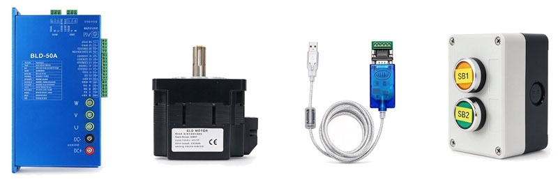
Components Required
Prepare the following components before starting:
- BLDC motor
- BLDC motor controller
- 24V DC switching power supply
- USB-to-RS485 converter
- Two self-latching buttons (SB1 and SB2)
- PC with the controller configuration software
The RS485 connection is used to communicate with the controller and configure motor parameters, while the two external buttons provide input signals for selecting different speed segments.
BLDC Motor Controller Wiring
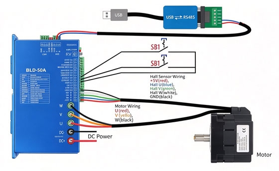
Before configuring the controller, connect the motor, power supply, buttons, and RS485 converter.
Connect the Motor and Power Supply
Connect the 24V DC power supply to the motor controller's power input terminals. Then, connect the three motor phase wires to the motor controller's U, V, and W terminals. If the BLDC electric motor uses internal Hall sensors, connect the Hall sensor wires to the corresponding terminals on the motor controller.
Connect the Self-Latching Buttons
Connect the two self-latching buttons to the motor controller's digital input terminals:
- SB1: Connect to X1.
- SB2: Connect to X2.
- COM: Connect the common side of both buttons to the motor controller's COM terminal.
These inputs are used to select different speed segments according to the motor controller's configuration.
Connect the RS485 Converter
Connect the USB-to-RS485 converter to the controller's RS485 communication terminals.
- A: RS485 positive terminal
- B: RS485 negative terminal
Plug the USB end of the converter into your PC.
Check the terminal markings on your motor driver before connecting, as RS485 terminal naming and polarity conventions may vary between devices.
Controller DIP Switch Settings
Before configuring the motor, disable the RV potentiometer input on the controller.
For the controller used in this demonstration, set:
- DIP Switch 1: OFF
- DIP Switch 2: OFF
These settings apply to the electric motor controller shown in the video. Check your controller's manual for the corresponding settings if you are using a different model.
Multi-Segment Speed Configuration
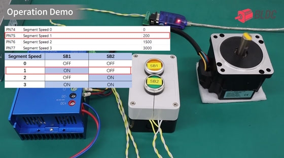
The two self-latching buttons provide four possible ON/OFF combinations. Three combinations are assigned to preset speed segments, while switching both buttons OFF stops the motor.
The operating logic is shown below:
| SB1 | SB2 | Motor operation |
| OFF | OFF | Stop |
| ON | OFF | Speed 1 |
| OFF | ON | Speed 2 |
| ON | ON | Speed 3 |
The actual speed and direction of each segment are determined by the controller's parameter settings.
RS485 Communication Setup
After completing the wiring, power up the controller and connect the USB-to-RS485 converter to your PC. Open the controller configuration software, select the assigned COM port, and click Connect. The software will automatically detect the baud rate and load the controller parameters.
If the connection is successful, the software will display:
COM connect success
BLDC Motor Parameter Settings
Once communication is established, configure the following parameters in the software.
| Parameter | Setting | Function |
| PN14 | 6 | Assign segment speed as the data source |
| PN15 | 4 | Define segment speed as the control source |
| PN30 | 4 | Enable segment speed input |
| PN31 | 4 | Enable segment speed input |
| PN16 | 2 | Set closed-loop speed control mode |
| PN68 | Set as required | Configure maximum speed |
| PN74–PN89 | Set as required | Configure individual segment speeds |
Setting the Speed and Direction
PN74 to PN89 are used to configure the preset speeds for different segments.
- Positive value: Motor runs in the forward direction.
- Negative value: Motor runs in the reverse direction.
- Zero: Motor stops.
The maximum speed is limited by the value configured in PN68. Make sure the preset speeds remain within the controller's permitted operating range.
For example, you can assign 1000 RPM to Speed 1 and -1500 RPM to Speed 2 as an example. The BLDC motor will run forward at Speed 1 and reverse at Speed 2 when the corresponding button combinations are activated.
BLDC Motor Operation Test
After completing the wiring and parameter configuration, test the motor using the two self-latching buttons.
Follow the operation sequence demonstrated in the video:
- SB1 ON, SB2 OFF: The motor runs at the preset Speed 1.
- SB1 OFF, SB2 ON: The motor switches to the preset Speed 2.
- SB1 ON, SB2 ON: The motor runs at the preset Speed 3.
- SB1 OFF, SB2 OFF: The motor stops.
The BLDC motor's rotation direction depends on the sign of the corresponding speed parameter. A positive value sets forward rotation, while a negative value sets reverse rotation.
Conclusion
By combining RS485 communication with two self-latching buttons, this setup allows users to switch between three preset BLDC motor speed segments and configure forward or reverse rotation through software. It provides a practical control method for applications that require multiple preset speeds and direction switching.


